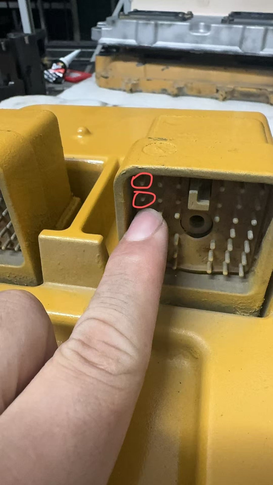
Exterior inspection
We inspect the housing, connector, pins and visible damage before powering the ECM.
ECM repair
Every repair starts with the case, connector and board condition. We confirm communication, open the module when needed, then locate the exact power, chip, driver or hardware fault before repair.
Step-by-step workflow
We inspect the housing, connector, pins and visible damage before powering the ECM.
The ECM is connected to a computer or bench tool to confirm whether it can communicate and report codes.
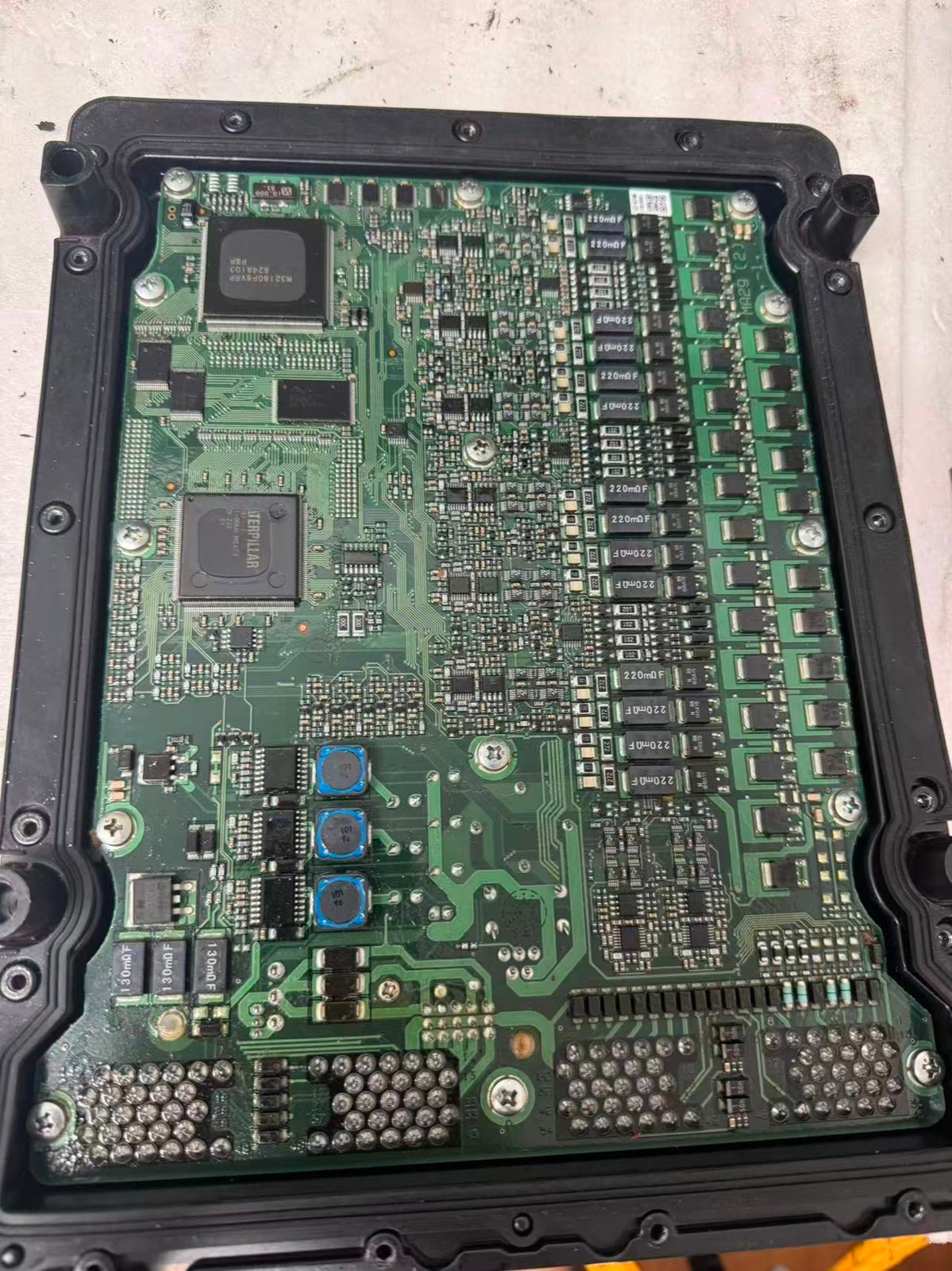
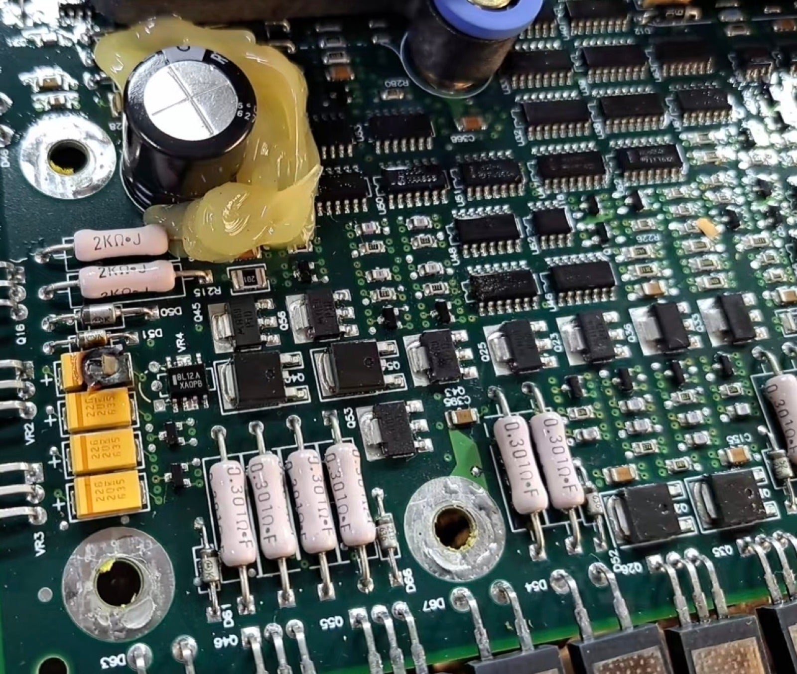
If communication fails or faults are confirmed, the module is opened and the board is tested component by component.
Faulty power, chip, driver or hardware areas are repaired before the ECM moves to programming and final testing.
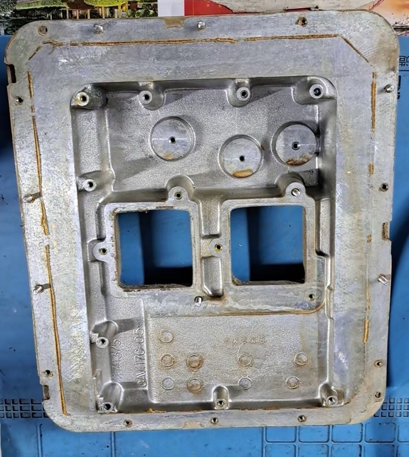
Workshop proof
These photos show the casing, opened board and fault areas customers care about before approving repair.
Repair confirmation
Share the ECM label, connector condition, machine model and failure symptoms. We confirm the repair path before deeper work.